Welcome to the #1 Online Parts Store!
Welcome to the #2 Online Parts Store!
Welcome to the #3 Online Parts Store!
Given the light weight and compact design of modern engines, we estimated that the generator would have to be no more than 100mm (4 inches) in diameter, 20 mm in length, and produce approximately 700 watts (W) per kilogram (almost 1 hp per pound) of generator weight.
Stator Core. A three-phase, nine-pole, six-magnet design with a double lap-wound stator and permanent magnet rotor was selected. Operating generator speed would be directly proportional to engine speed, with a range of 4,000 to 17,000 rpm.
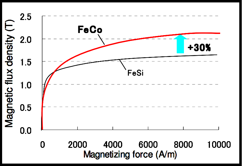
An initial concern, particularly given the high generator speed, was the effect of iron losses in the stator core, which is typically an AC generators heaviest component. Conventional grain-oriented silicon steel was not efficient enough to be used in a generator that would meet our project’s generator size and weight targets, and an iron-cobalt alloy (49Fe-49Co-2V) was used to produce the generators stator core laminations. This yielded a 30% increase in flux density.
 |
|
Relative magnetic flux densities of 49Fe-49Co-2V iron-cobalt alloy, as compared to more common silicon steel. |
The iron-cobalt alloy’s iron losses were further reduced via a combination of technologies. A post-rolling heat treatment reduced core hysteresis losses, and an ultra-thin oxidized insulation coating was developed, which allowed us to reduce stator core lamination thickness to one and a half tenths of a millimetre per lamination while preserving the desired iron-to-insulation ratio. These refinements reduced the alloy’s iron losses by a further 60%.
 |
|
The magnetic flux density of our iron- cobalt alloy was increased through multiple refinements. |
The maximum current frequency for a 17,000 rpm nine-pole generator, (assuming an equal number of poles in both rotor and stator), is 580Hz, this causes extremely fast transients, creating voltage stresses within the winding. Not surprisingly, the stator winding was wound with scratch-resistant inverter duty wire to reduce the possibility of pinholes created during the manufacturing and/or winding process, and therefore reduce the possibility of winding failure.
Rotor Design. We used a high-coercivity magnet with an intrinsic coercivity of at least 1.1 Ma/m at 160ºC, to minimize temperature increases and resultant eddy current losses, six magnets were used in the rotor’s interior configuration.
Rotor diameter was reduced further to 45mm, by employing the rotor’s shaft as part of the rotor flux circuits. A high tensile steel band encloses the rotor, preventing magnet burst at the centrifugal forces produced at the rotor’s 18,000 rpm redline. The rotor’s tapered mounting assists heat conduction and close tolerances help with utilising flux conduction from the shaft hence reducing losses.
The final generator design (although being continuously improved) is cooled by engine oil, with stator cooling passages around the circumference of the hard anodised cup. The windings and core worked out at 80mm in diameter, and the rotor 19mm long, exceeding our initial design.